Hot Side, Crank Position and Speed Sensors, Flywheel and Clutch

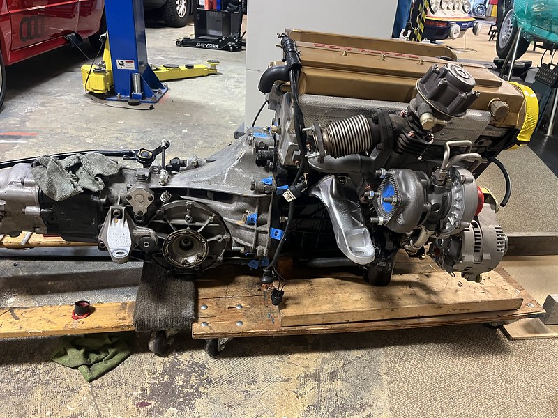
Last time we talked we installed the throttle body, split the engine from transmission, refinished the engine mount brackets, installed the coolant and intake manifolds and got distracted by the foot rests. This week we’ll go over how we struggled to install the exhaust manifold, wastegate and turbo, made the crank position and speed sensors fit and installed the flywheel and clutch.

The exhaust manifold bolts were a bit fiddley and some are hard to reach with normal tools but we persevered and got them all torqued down too! The turbo and wastegate nuts were a lot more accessible though (ignore the alternator, that never happened.)

Close-up view of an engine block with attached components including intake manifold and piping, set in a garage environment.
A close-up view of an engine block with various components such as an intake manifold, fuel injectors, and wiring.
A detailed view of an automotive engine mounted on a stand, showcasing various components including a turbocharger, alternator, and wiring, with a toolbox visible in the foreground.

As we are using a 20 valve AAN engine with a 10 valve Quattro transmission (016 apparently) our AAN speed and crank position sensors would not fit as they are in different locations than on the 016. But we love an opportunity to get the grinder out!

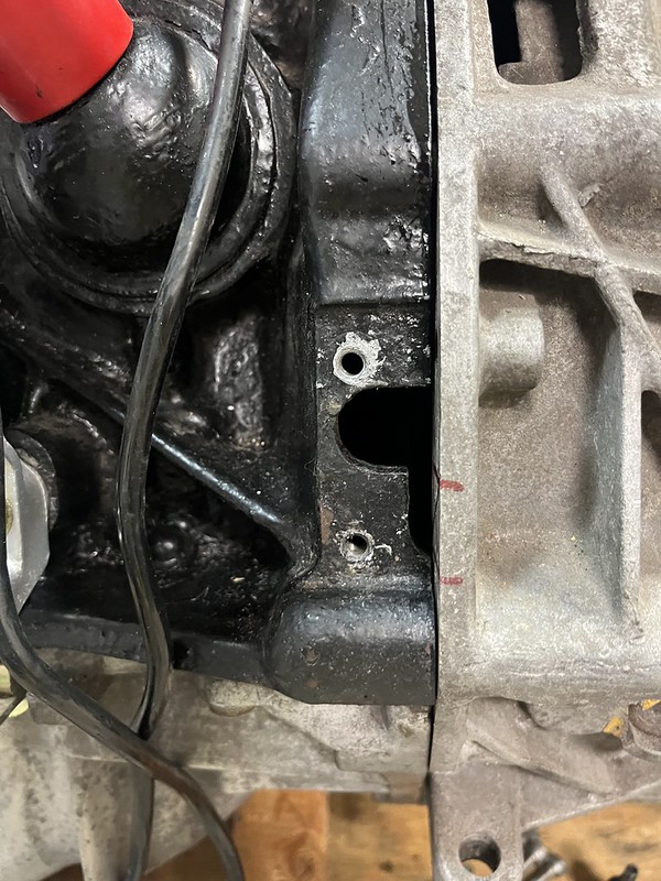
Close-up view of a mechanical component, possibly a sensor or valve, with visible wear and corrosion, set in a workshop environment.
Close-up of an engine block showing various components, including a blackened area and exposed holes. Electrical wires are visible alongside the parts.
Close-up view of engine components, showcasing two black sensors connected by wires on a metallic surface.
Close-up of a metal component with marking and holes, set in a workshop environment.
Close-up view of an automotive engine component, showcasing intricate details including screws, wires, and various mechanical parts.
A person wearing gloves uses a tool to work on an engine part that has blue tape applied to it, showcasing an assembly with various mechanical components.
Close-up view of a mechanical component, showcasing detailed textures and surfaces with distinct openings and machined edges.
Close-up of an engine component showing various parts including a sensor connector, metallic surfaces, and wiring.


Again, the AAN and 016 combination through us a wobbly as we needed the right combination of components so they’d get along. However, we went with a kit from Ringer Racing so we wouldn’t have to think too much.

A disassembled clutch kit featuring a clutch pressure plate, clutch disc, and release bearing, arranged on a white background.
Close-up view of an engine assembly showing a flywheel with blue tape labels and a red component, mounted on a silver engine block.
Close-up view of a car clutch assembly, featuring a gray pressure plate and various mechanical components, with blue painter's tape applied for protection.


Then we reintroduced the engine to the transmission. They sure had missed each other and now seem like they don’t want to ever let each other go. Awww!
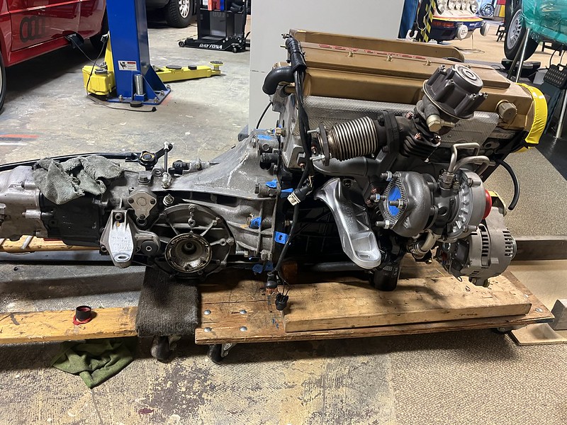
A disassembled engine and transmission on a wooden platform, featuring various mechanical components and tools in a workshop setting.

Subscribe for more updates or follow us on Instagram, Facebook and YouTube as we push to get this engine in the car and fired up. 
 

Leave a Reply